Author Topic: Build Question - 20 pin header connections (only given 8 in my Van Daal kit)  (Read 4803 times)

kylelandstra

  • Team member
  • *
  • Posts: 16
    • View Profile
Hi all,

I'm relatively new to DIY electronics so please forgive me.  My question is in regards to the "Regular for Jmp1-3 and the rest" below.  As a note, I had purchased mine from Van Daal.


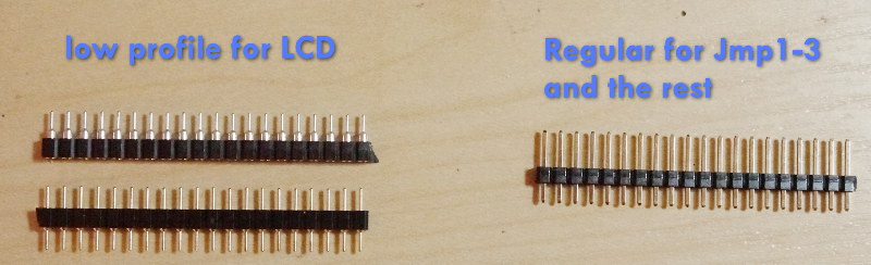
I was only given 8 of those pins out of the 20 shown on the right hand side of the photo.  So far I have soldered 2 on for the Jmp1 and 2 for the Jmp2.  From the directions it states Jmp3 is not required, but only for the DFU.  So would I need to solder/unsolder the Jmp3 every time I need to update the firmware?  Or just for the first time I turn it on?  Or not required at all?


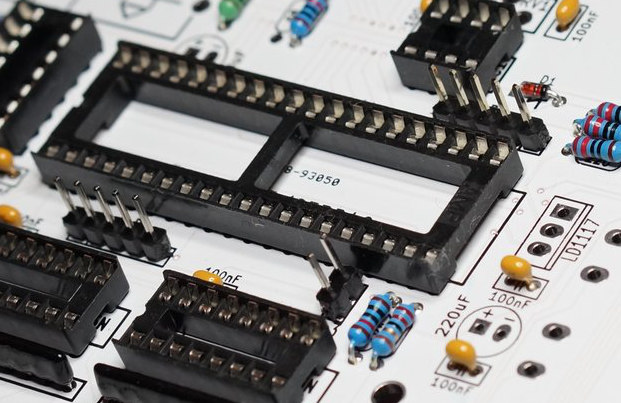
Secondly, in the photo below, it shows various pin headers (two 5 pin headers, one 2 pin header) connected yet in the directions it states that these are "optional".  Is that true that these shown below are not required?


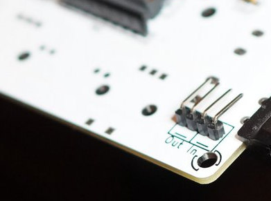
Since I was only given an 8 pin stick for headers, you may see my dilemma.  Luckily if only the Jmp1 and Jmp2 are required, I would have just enough pins left for the In/Out (pictured below).


Once again, I appreciate the help.  Please forgive me if these are newbie questions, but with this being my first synth I've built and seemingly not given enough header pins to work with, I want to make sure I do it right. 

Thanks,
Kyle
« Last Edit: January 26, 2017, 04:07:00 AM by kylelandstra »

Xavier

  • Administrator
  • Hero Member
  • *
  • Posts: 2257
    • View Profile
Hi,

You only need to solder headers on JMP1 and JMP2.

JMP3 if you need to flash the bootloader one day.  bootloader is different from firmware.
You'll likelyt never need it.
You don't need it at all to upgrade firmware.
http://ixox.fr/preenfm2/manual/upgrade-firmware/

You don't solder/unsolder the pins. You just put or remove the jumber on it.

The others P1, P3 are for specific purpose..
. P1 allows you to plug a st-link v2 debugger.
. P3 analog input  (require dedicated firmware).

Xavier

kylelandstra

  • Team member
  • *
  • Posts: 16
    • View Profile
So P1 and P3 are not required?  I don't plan on using a st-link v2 debugger.  And what does P3 analog input (require dedicated firmware) mean?

Xavier

  • Administrator
  • Hero Member
  • *
  • Posts: 2257
    • View Profile
And what does P3 analog input (require dedicated firmware) mean?

https://github.com/Ixox/preenfm2/tree/adcIn
If you compile the branch adcIn from github.
You'll get 4 additional analog entries in the modulation matrix. !!!! 0-3.3v or you'll break your preenF405 !!!!
No support from me on this firmware.
If someone come up with a clean op amp schema to plug some external analog hardware here, i'm interested  ;)

kylelandstra

  • Team member
  • *
  • Posts: 16
    • View Profile
Thanks for the guidance Xavier!