Here is a guide to help you build the preenfm2 with PCB R6.
If you ordered a pfm2 full kit, all components should be contained in the package.
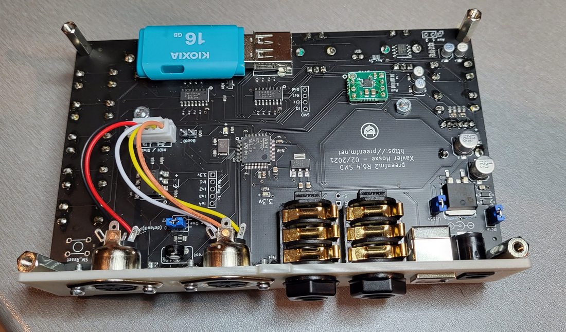
First, you can start soldering the DAC tiny board with the 2 x 4 pins headers.
Insert the 2 headers in the main board, put the DAC board on the top. Solder the top.
Turn the 2 boards and solder the 2 x 4 headers on the other side. You can cut the 8 pins on the back as they can be a bit long.
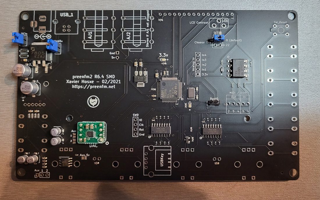
4 x 2 pins jumpers : then continue with the regular 2.54mm headers, cut 4 x 2pins, 3 of them must have the jumper on them as shown on this picture.
See the blue jumpers bellow. The 4th open header is for « boot0″. Just on the right of the center CPU. « Boot0″ is usefull if you want to flash the bootloader. Useless to flash the firmware though.
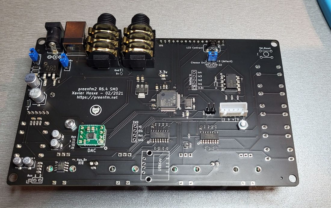
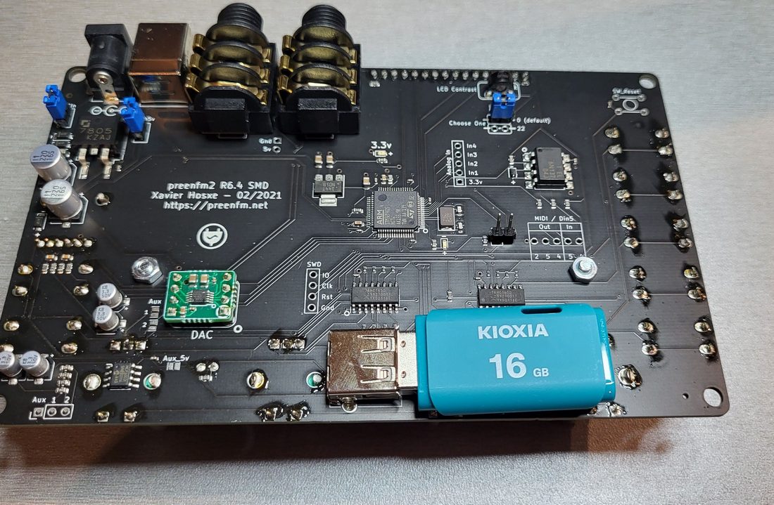
Now solder the DCIn socket, the USB, the 2 Audio Jacks , the variable 3 pins resistor (LCD contrast), and the 5 pins white socket (Midi / Din5).
Don’t solder the USB socket for the USB stick now. It’s better to do that later.
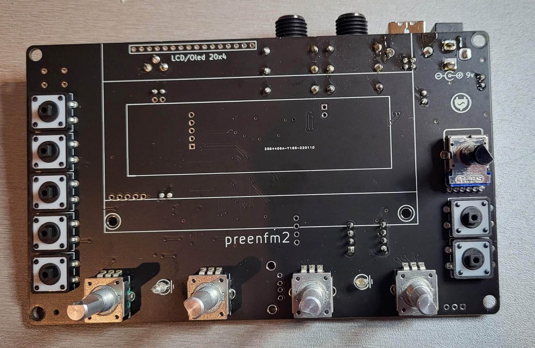
On the other side you’ll have to solder the 4 encoders, the 7 buttons, and the 6 pins pot for the volume.
Don’t forget the 2 leds between the encoders, they will add some rythm when the preenfm receives midi clock (Mind the minus (-) pins)
Before soldering each piece, make sure it’s well positioned against the main board.
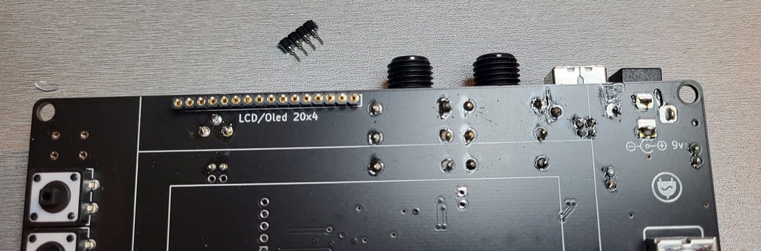
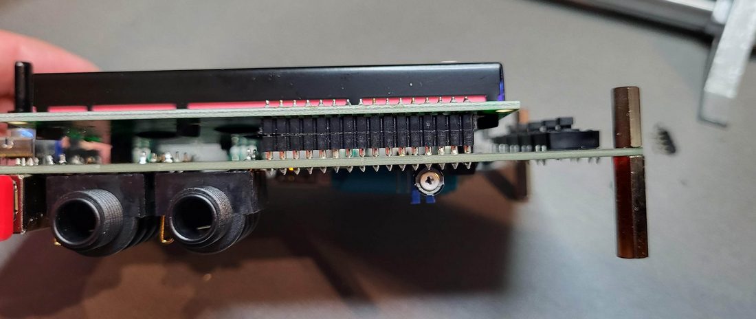
For the LCD/Oled , you’ll have to cut out 4 pins and keep 16.
Start with soldering only one pin, make sure the orientation is fine (perpendicular to the board), and that it’s well tighten against the main board.
Then solder the other 15 pins.
Now you can solder the USB socket for the stick on the other side.
Make sure you’ve cut the encoders pins close to the board.
Last advice, it’s easier to solder with the Stick inserted.
Before doing that, copy the ‘pfm2/’ folder on the USB stick. more information here : https://ixox.fr/preenfm2/download/
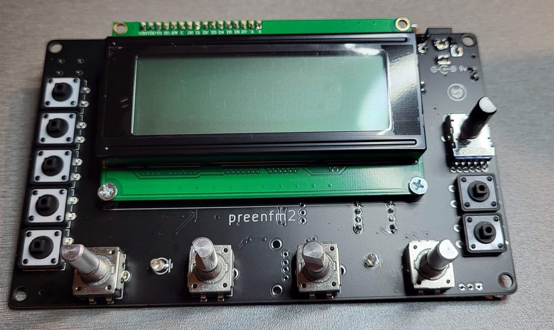
Solder the low profile male header to the LCD. Also be carefull with the orientation, it must be well perpendicular to the LCD PCB.
And you can insert it in the female header, and secure it with the 2 screws+nuts+small spacer.
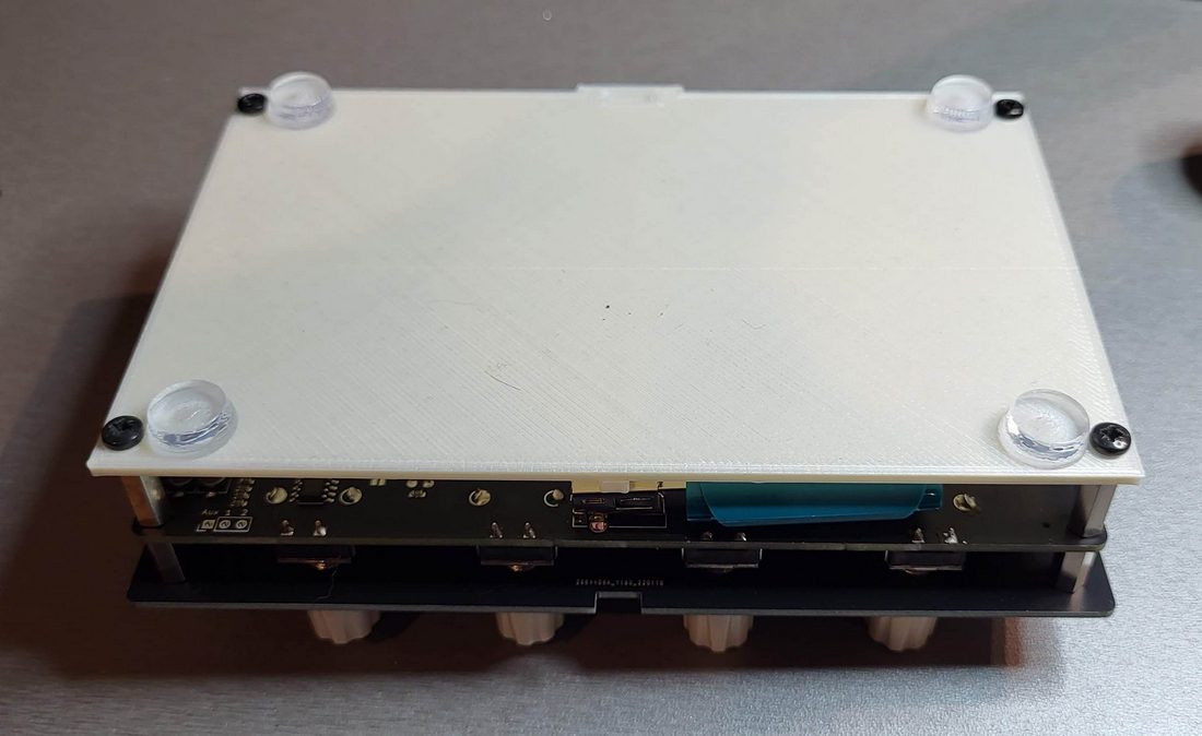
Now you can install the 8 metal hexa spacers.
The 4 Female/Female 12mm are on the top.
The 2 M/F 20mm are for the bottom rear.
The 2 M/F 15mm are for the bottom front.
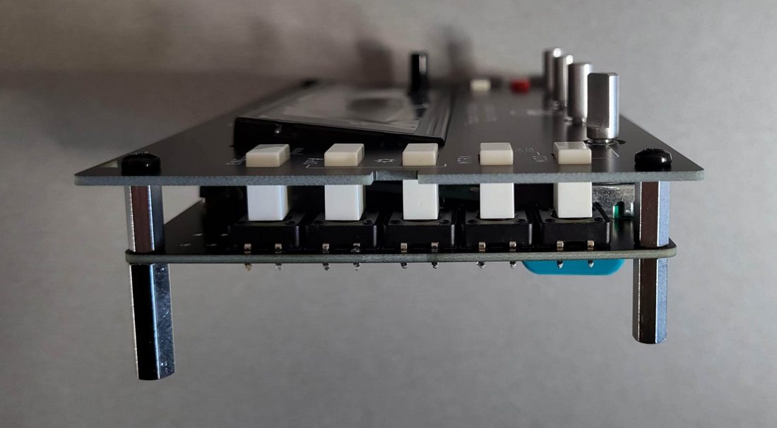
Then add the White/Black top surface. Insert the button, and make sure the buttons are well perpendicular to the PCB/Top surface.
If they’re not perpendicular, you can try to losen a little the hexa spacers, and move them a little before tighten them.
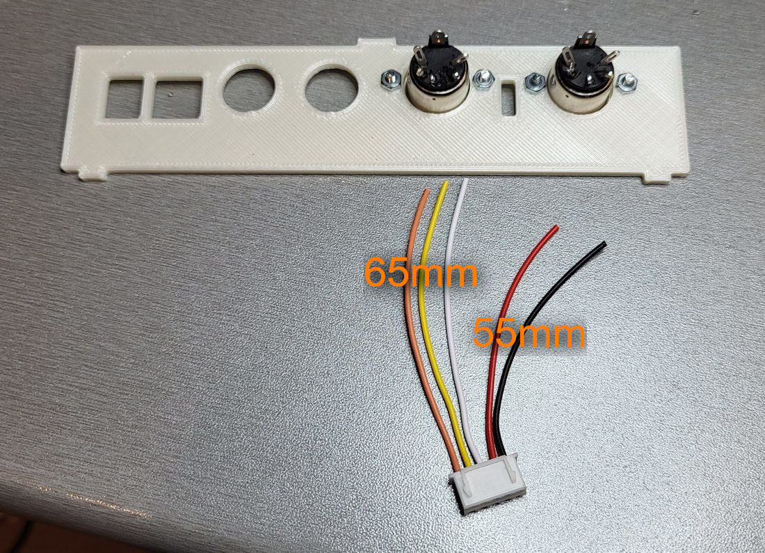
Now you can prepare the back panel with the DIN 5 midi connector.
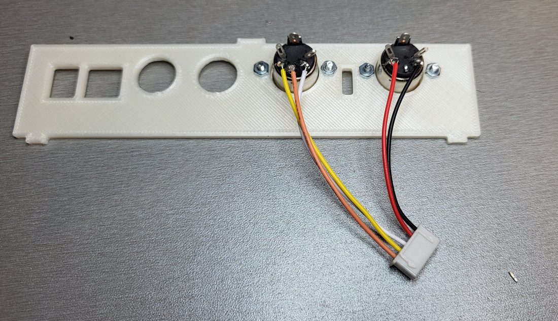
Install the back panel, secure with the audio jack plastic screws and insert the Din5 header in the while socket.
Take the bottom panel and use the 4 remaining M3 screws to fix it.
Stick the 4 plastic feet.
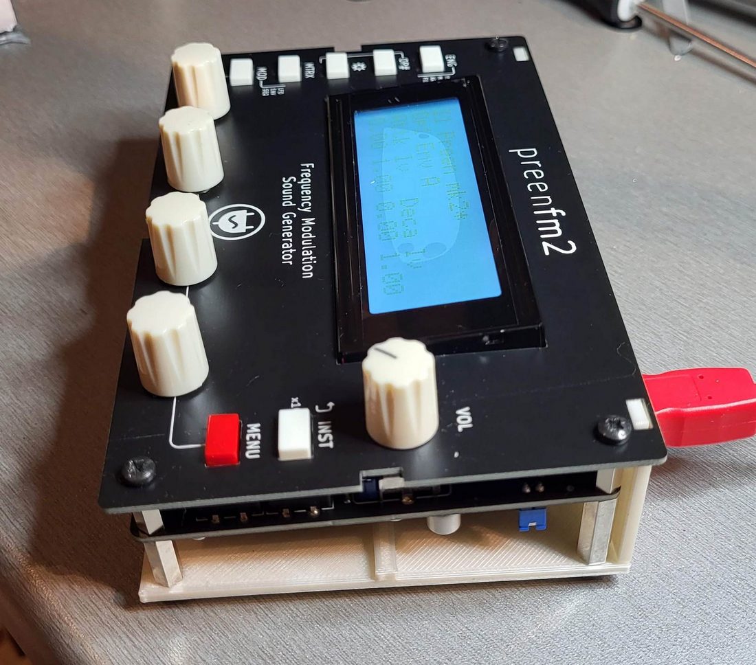
Add the knobs on the top.
The first time you insert them, that can be a bit hard.
As the front panel is open, you can maintain the PCB with your finger while pressing the knobs on the top.
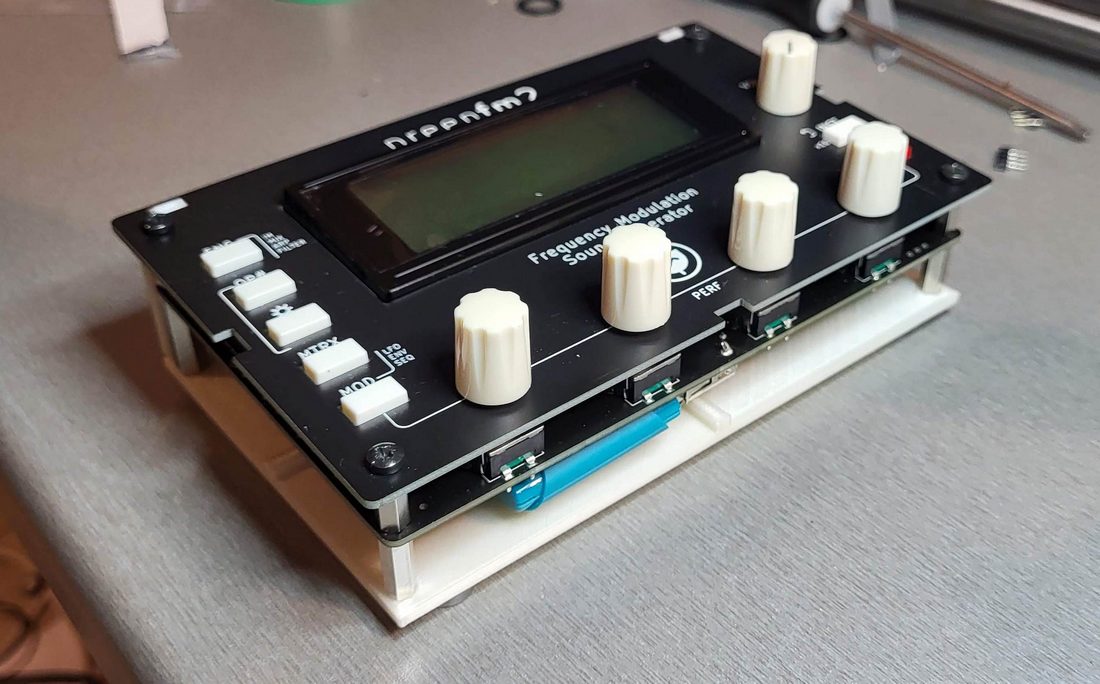
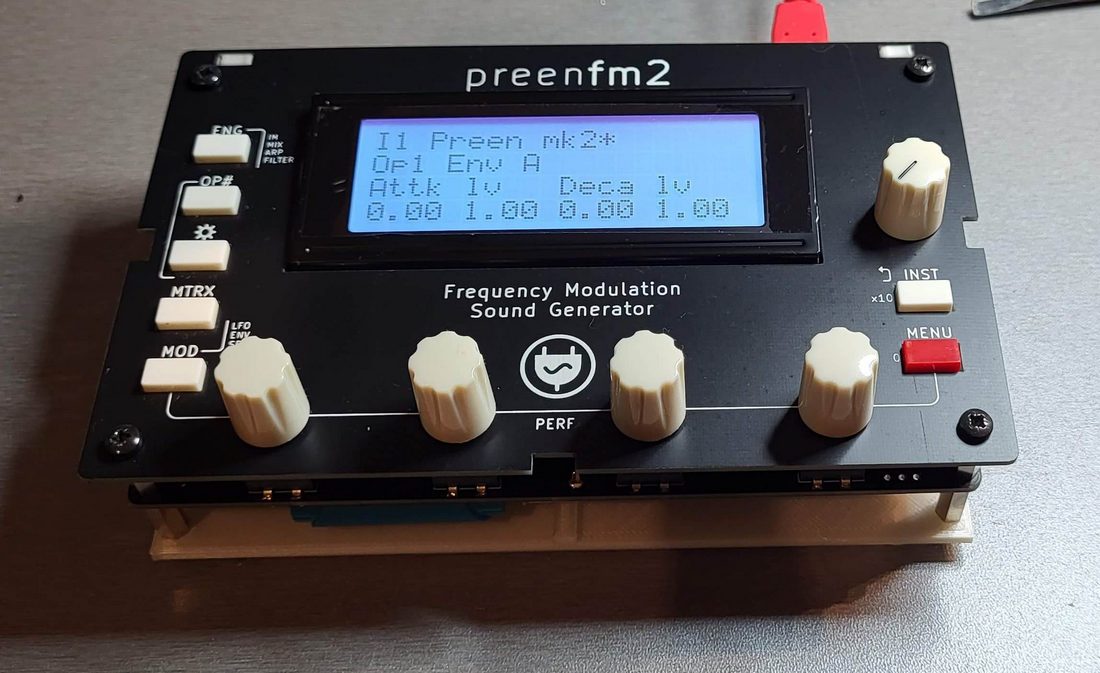
Now you can power on the preenfm2.
Use a 9v (500mA min / ground outside) 2.1mm wall adapter or a USB cable that allows power and midi interface at the same time.
The first time you switch it on, you’ll likely have to adjust the LCD contrast with the variable resistence accessible from the rear panel with a tiny screw driver.