The PCB R6 comes with many SMD presoldered components which makes the build faster and easier than the previous versions.
The only real difference in the components, is its 24 bits stereo DAC.
It requires the firmware 2.20 or newer.
To flash the bootloader on this PCB. You can follow these instructions.
Components that you still need are listed in the BOM here.
The bottom of the PCB R5 instruction as well as the Case build manual can help if you need more details.
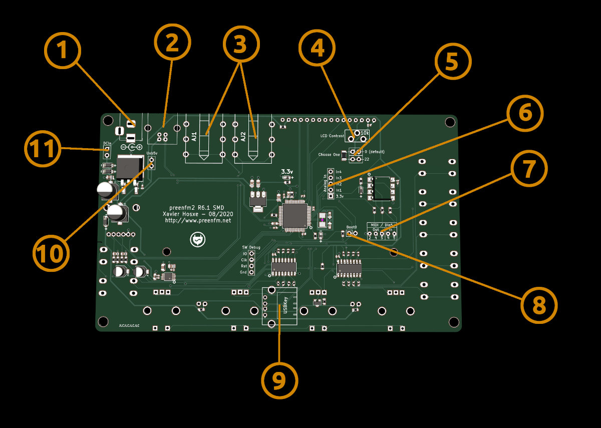
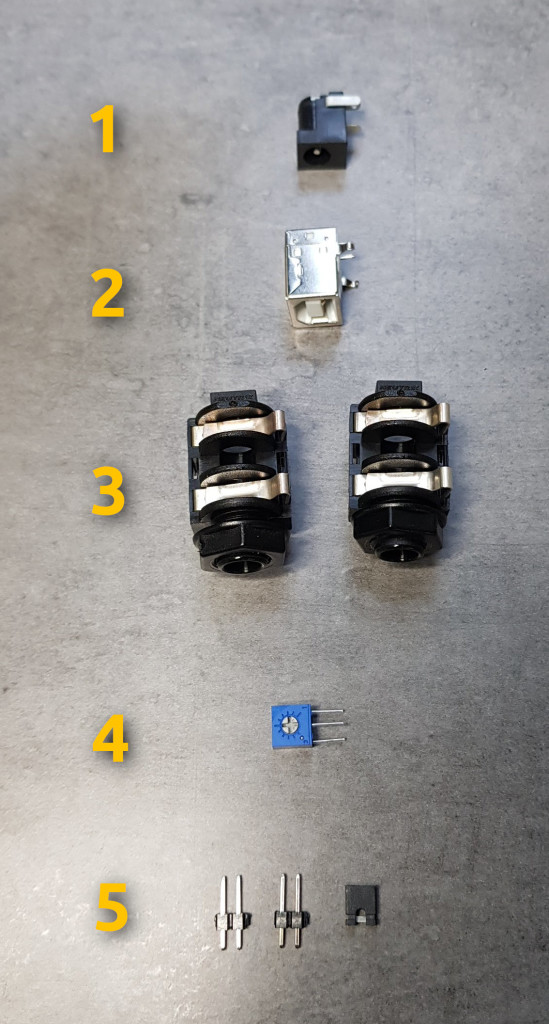
- (1) DC poxer jack (ref mouser 163-7620E-E)
- (2) USB Type B connector (ref mouser 710-61400416121)
- (3) Audio JackNeutrik NMJ6HFD2 (or NMJ6HFD2-AU for gold contact). Output 2 is stereo if no jack in output 1.
- (4) Contrast adjust for LCD display (not OLED) such as PT6KH-103A2020
- (5) Short the 0 Ohm connection by default / If you want the mod to mitigate the 13.5Khz of the yellow OLED, short the 22 Ohm connection.
- (6) Analog in connector
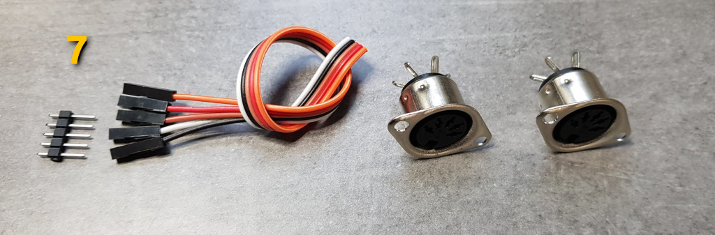
- (7) Midi connector to connect to 2 DIN 5 Jacks (Mouser ref 568-NYS325)
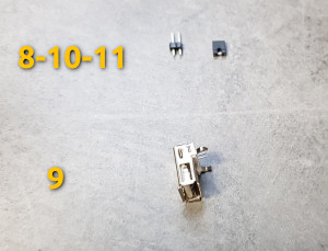
- (8) You’ll need to short that with a jumper to flash the bootloader once.
- (9) USB Type A connector for the USB Key (Mouser ref 710-61400416021)
- (10) USB power connection. To leave open if you use DC power AND USB midi, to avoid noisy USB 5v to reach the audio path. Short if you want to power from USB.
- (11) Short or insert a switch to power on/off your preenfm2.
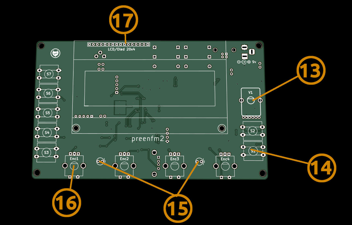
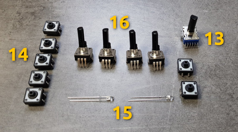
- (13) Volume pot (Mouser Ref 688-RK12L12C0A0E)
- (14) Button switch TL1100F160Q. You need 7 ot them.
- (15) 2 leds that can blink with your midi clock (blue ones are nice such as the mouser ref 604-WP710A10QBC/D)
- (16) rotary encoder. PEC11R-4220F-S0024 or PEC12R-4225F-S0024. The switch is optional and is not very important in the preenfm2 usage.
- (17) OLED or LCD such as this one.