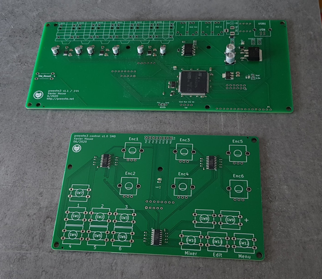
The preenfm3 comes on 2 pre-solder SMD PCBs. Presoldered but you still have to add different components.
On the main PCB you need to add different headers, jumbers and solder the audio, midi, usb and dcIn sockets.
On the control board you’ll have to solder encoders, and switches
Then every thing must be put into a box.
PART 1
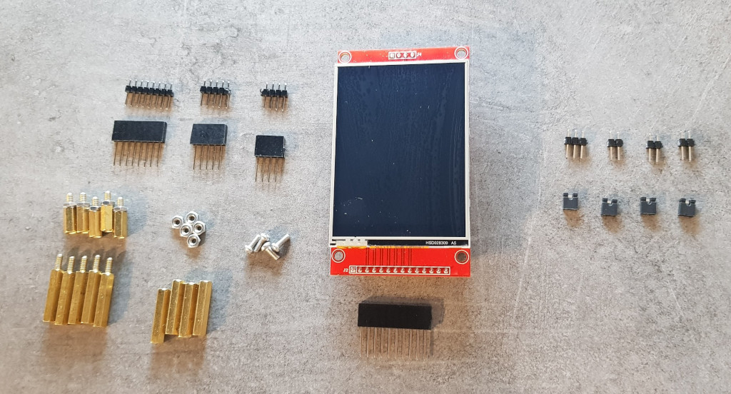
The following can be M2.5 or M3 :
- Hex spacers F/F 20mm * 4
- Hex spacers M/F 12mm (10mm + nut on the picture) * 5.
- Nuts * 5
- Screws 6mm * 4
Update : I finaly think it’s better to have 5 F/F 12mm spacers and replace the 5 nuts by 5 screws 6mm.
So the list would be :
- Hex spacers F/F 20mm * 4
- Hex spacers F/F 12mm (10mm + nut on the picture) * 5.
- Screws 6mm * 9
Long leg / stackable headers
- 10+ pins for the TFT (can be between 10 and 16)
- 4 pins for the TFT (6 pins works if you remove manually 2 pins)
- 8 pins for the control board
- 5 pins for the control board ((6 pins works if you remove manually 1 pins)
Other headers and jumpers
- 2 pins male header for the USB ground connection
- 2 pins male header for the USB 5v connection
- 2 pins male header for the DCIn 9v connection
- 3 pins male header for the boot0
- 4 Jumpers
TFT
- 2.8″ ili9341 TFT (without touch are nicer)
Only 9 pins are used on the bottom header of the TFT (No touch)
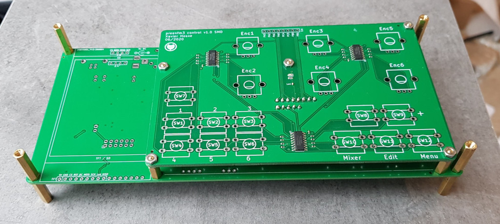
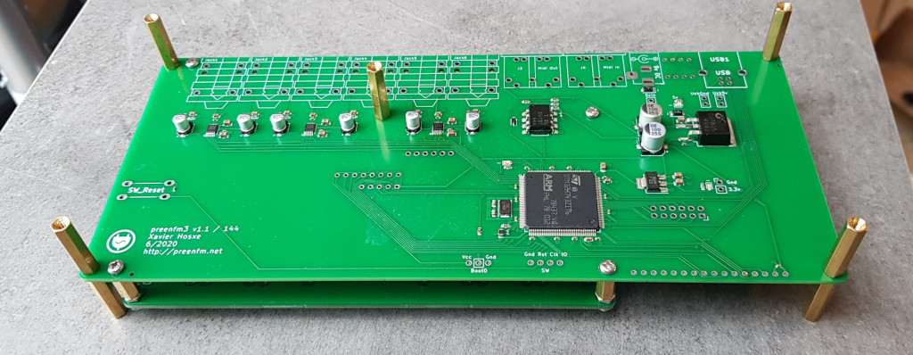
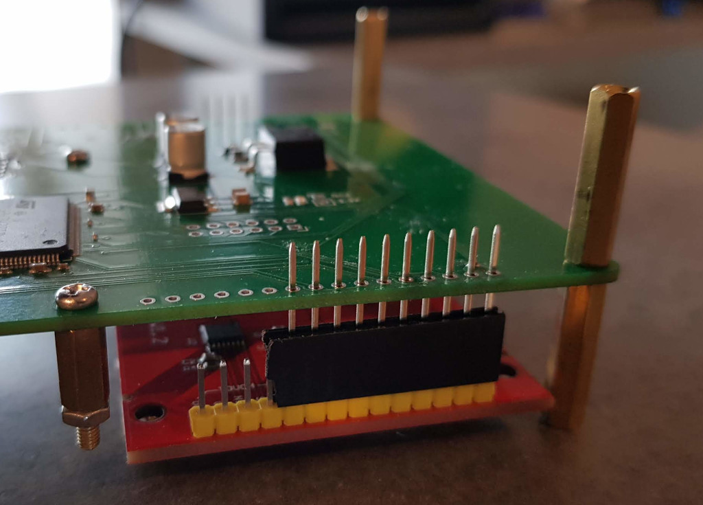
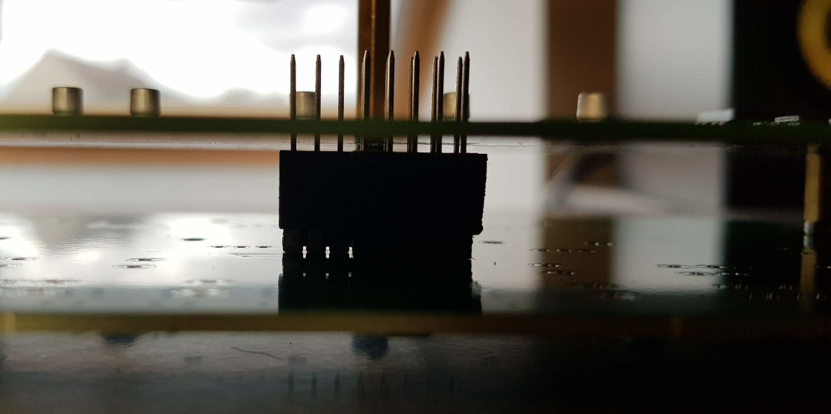
Here is how to use those spacers :
Why do we have to use long legs / stackable header ?
The main PCB to Control board distance is too long for regular header (a bit too long).
The TFT is much nicer when close to the enclosure surface, so the main PCB to TFT distance is too long for regular header.
All long legs have to be soldered after everything is assembled to adjust the space between the start of the plastic and the main PCB.
For the TFT, the 4 * 20mm hex spacer help knowing which distance is needed. (insert something (~1mm) under the TFT if you need additional protection between your TFT and the final enclosure)
Make sure you solder with one header at least the 9 pins that have a reference on the preenfm3 PCB. So you need a 10+ pins long leg header.
Other pins are not used but can be solder without any problem.
For the control board, the need is more subtile. But the long legs help to get a nice soldering.
PART 2
Here is the BOM of the control surface
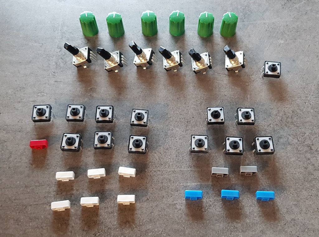
- Encoders PEC12R-4220F-N0024 * 6 (PEC12R-4220F-N0012 also work)
- Switch TL1100F160Q * 13 (12 for he control surface + 1 optional one for the reset button on the back)
- Any button that fits the encoders
- e-switch serie 5j *12 (choose your color)
No particular instruction to solder this components. Just put them on the correct side of the control board.
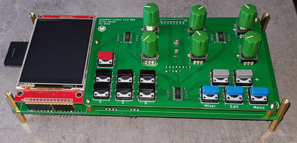
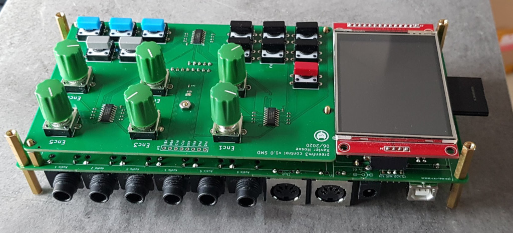
Picture of the finished control board :
PART 3
External connections :
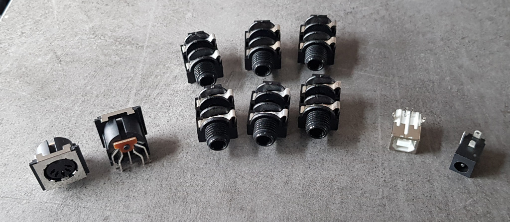
- Din 5 PCB mount midi jack * 2(such as this one)
- Neutrik NRJ4HH * 6 (audio jack)
- Usb Type B PCB sock (like this)
- DcIn socket (like this)
- A regular size SD card (Not on the picture)
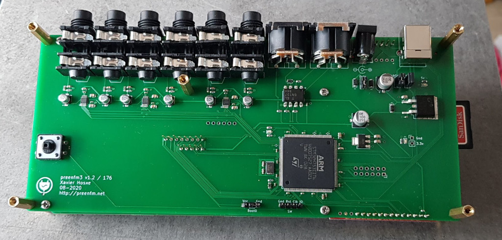
So the finished assembled PCBs look like :
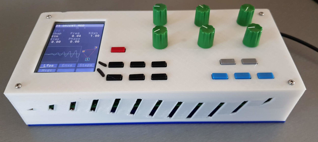
And in the 3D printed case :
