The PreenFM2 is an easy to build kit, should take between 2 to 3 houres, less if you’re experienced.
First, please check the BOM and make sure nothing is missing.
Then 2 things to take care of :
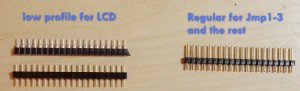
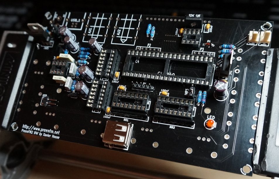
1 . Don’t mix the 20 pins regular male header with the 20 pins low-profile male and female header.
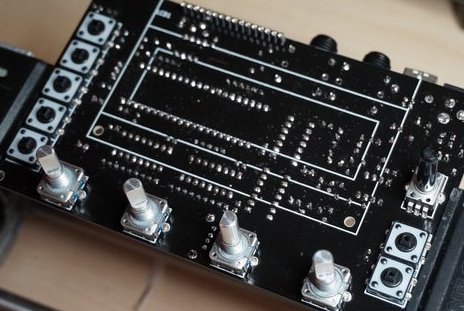
2 . Keep in mind that most components will be solder on the front side except :
The LCD connector
The volume pot
The 4 rotary encoders
The 7 switches
The rest is on the front side. It happened to me to solder the volume pot on the wrong side in the hurry, it was very difficult to unsolder it.
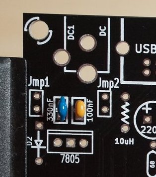
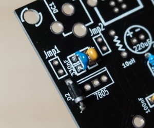
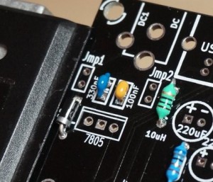
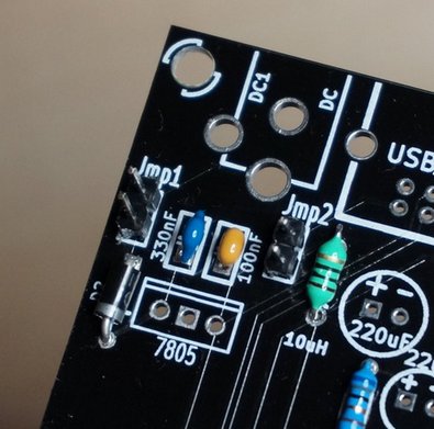
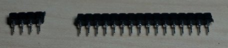
OK, that being said, let’s start by soldering the 9 declouping 100nF capacitors.
Then you can go with the 330nF that is recommanded in the 7805 regulator spec.
After that, you can sodler the resistors, take the resitor sheet :
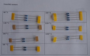
Respecting this order is an easy way to solder them all :
68 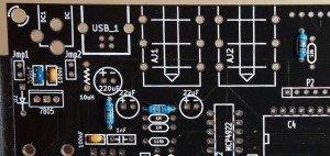
220
1.8K
8.2K
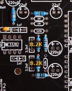
Then the 115K :
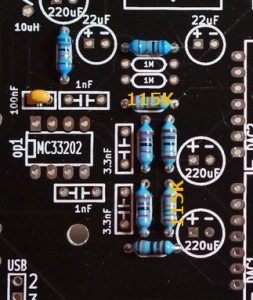
And the 1M :
And then, you should have 2 10K left :
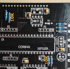
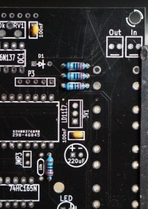
Now you can put the 2 diodes, D1 is the small red one, D2 the bigger black and white.
Orientation is very important, don’t miss the black ring on D1 that must respect the orientation drawn on the PCB.
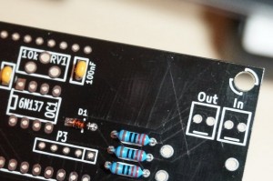
And the inductor (looks like a resistor but greener ![]() that is in the plastic bag with the diodes :
that is in the plastic bag with the diodes :
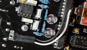
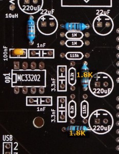
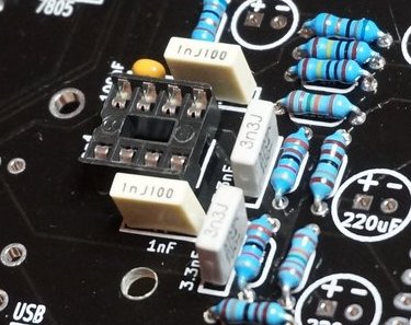
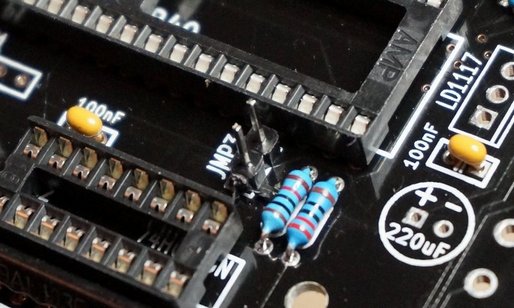
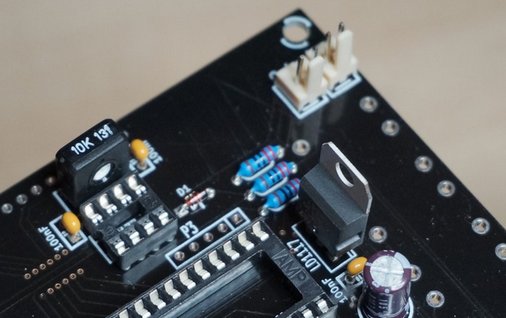
Then take the 2 resistor networks and put them like on this picture, the orientation is VERY important. The triangle of the 9 pins resistors must be over the left pin of the PCB (the pin that is alone in the white square).
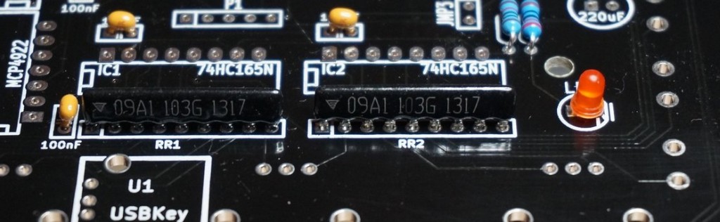
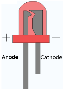
On the above picture we also added the LED. The minus of the led is specified on the PCB (the right pin).
The minus of the led is the shorter pin.. Give a look at this if you hesitate : http://www.thediyworld.com/How-To-Properly-Use-LEDs.php
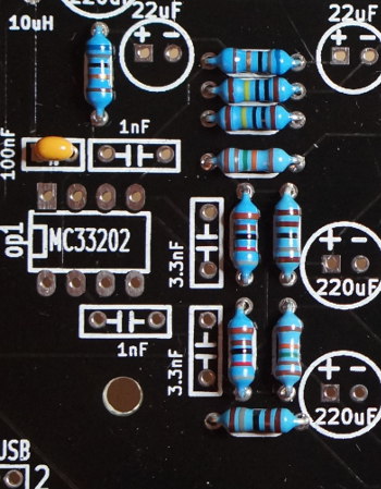
Now let’s solder the operational amplifer and its 4 plastic capacitors. With the resistors around, it acts as a low pass filter (20Khz).
And the other DIP8, DIP14 *2, DIP16 *2 and DIP40 sockets. Respect the orientation so that it’s easier to put the ICs in the right orientation too later.
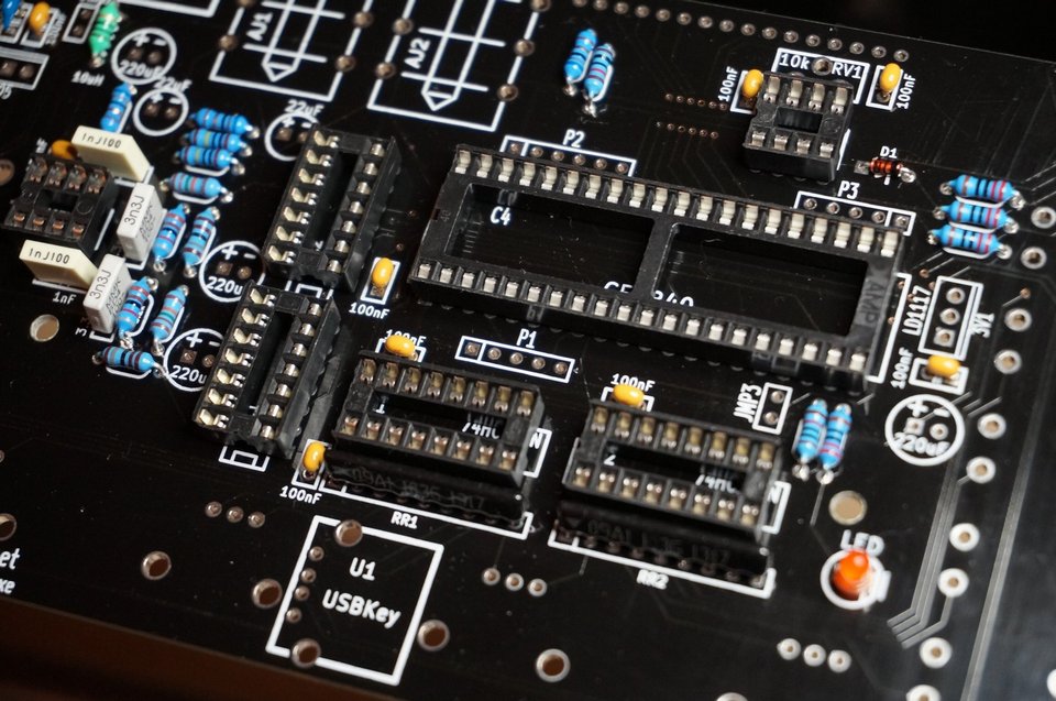
Now you can solder the 3 jumpers.
Take the 20 pins male header you get in the Kit and cut it. Don’t mix with the male and femele LCD connectors :
Jmp1 : The main current pass through this 2 pins. If you want to add a power switch this is the place. In any other case you want to have a connection here.
Jmp2 : This is the current from the USB plug. The 5V from the USB pass through it. If you want to enjoy the midi over USB while using a wall power supply (for exemple to control the PreenFM from an Ipod/Iphone/Ipad), it’s better to open Jmp2. That will avoid the 5V of the USB to be connected to the 5V of the regulator that can be a bit different.
In most case, you want the USB to power the PreenFM2, so the 2 pins must be connected.
Jmp3 : if connected, the PreenFM will boot in the DFU (Device Firmware Update) mode integrated in the STM32F4. Usefull to burn the firware for the first time. After this, the DFU mode can be reached from the surface controle.
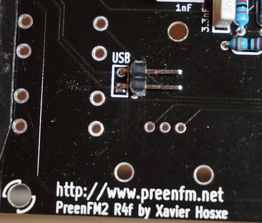
In the Kit there is a 2 pins right angle header. Spot the 2 pins USB on the PCB. These are the Data- and Data+ of the input USB plug. They will be redirected to the FEZ40 throught the cable we’ll build later.
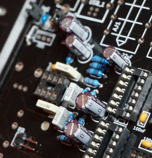
Now you can take the 6 electrolytic capacitors (2*22uF and 4*220uF). Mind the orientation, all the minus are in the same position.
5 of them are gathered on the left of the PCB.
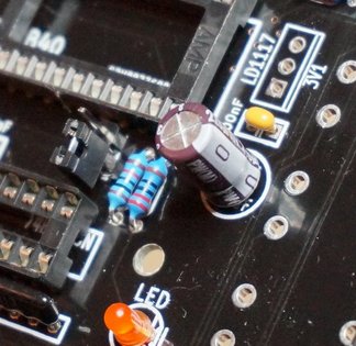
And the last 220uF one on the other side.
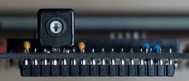
The 4 next steps consist in soldering the variable resisitor for the LCD contrast, the 2 male connectors for the midi connection, the 5V and the 3.3V regulator :
Variable resistor + 2 * 2 pins male connector (note that your variable resistor may look different – blue and smaller) :
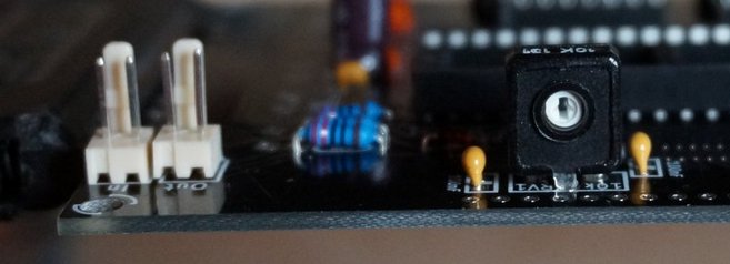
The 7805 – check twice it’s actually the 7805 :
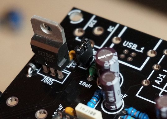
And the LD33 :
For the USB stick socket, be carefull with the angle. It may be a good idea to solder it withou your usb stick inside. Leave a small additional gap because later you’ll have an encoder bellow that will push a little the Usb stick.
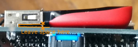
Then you can solder the USB socket for the usb stick and your PCB will look like this :
I found it easier to solder the 16 pins male header (LCD connector) at this point – Before the audio jacks are on.
In the kit you’ll find a 20 pins male and femele header. Cut them so that you have a 16 pins male and female header.
Flip the PCB over. Make sure it’s totally inserted inside the 16 PCB holes and completely against the PCB then solder it :
Flip the PCB over again and place the DC connector, the USB and the 2 audio jacks :
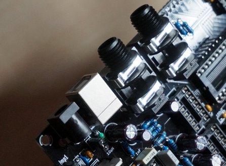
Then you’re done with this side.
The controle surface side is easier. Just be sure that all the components of this side are well in place before soldering.
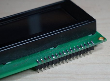
Solder the low profile male header to the LCD.
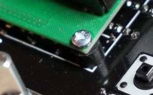
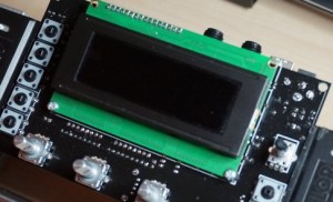
And insert it slowly in the 16 pins female header. In the bottom part use a 2 * 12mm screws + 2* 5mm plastic spacer to mantain the LCD.
And you have you controle surface ready :
Now you can put in place the ICs, respect the orientation and don’t swap the 6N137 and the MC3302. The rest cannot be swaped ![]()
Download the zip file example from the download page and extract it to you USB drive on your computer before inserting it.
At the same time you can fill the « pfm2/dx7″ firectory with up to 256 sysex DX7 bank files.
If you receive a CERB40 already flashed check you have the last firmware. If not: download the last firmware from the download page, extract the pfm2_*.bin file in « /pfm2″, then press « Op » button while switching on the PreenFM. Flash it. Et voila.
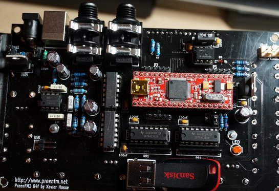
You have now to connect the CERB40 to the USB connector, use a DIY mini USB connector and 2 wires :
Nothing critical here but soldering this mini male USB is not easy. Maybe the hardest part of the preenFM.
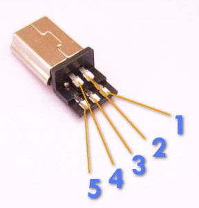
If you bought the USB connector on mouser the pin number are like this :
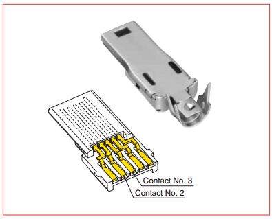
Only the pins 2 and 3 must be soldered and connected to the pins 2 and 3 of the PCB USB slot.
The pin 2 correspond to USB D-
The pin 3 correspond to USB D+
Ground and 5V are passed through the DIP40 pins so they are not part of this cable.
No need to keep a long cable, the wire can be cut at 5cm.