Last modification : January 12th 2016
THE BOM
To build a preenfm2 you need either a « full kit » or the following parts :
. the PCB (provided with USB drive, wires for midi JACK and low profile headers)
. The preenF405 (uController board).
. A Case (plexi or Metal) : svg files are here.
. USB cable type B or a 7.5-9v PSU . (USB cable allows midi transmission and usb drive access in adition to powering up the preenfm)
. The components :
Preenfm 2 BOM – make sure nothing is missing.
To fill you mouser card with the components go here (project number 7947c1face) :
https://www.mouser.com/ProjectManager/ProjectDetail.aspx?AccessID=7947c1face
Check the BOM with the spreadsheet just above.
The mouser project contains tac switch in black (TACBLK), replace them by TACWHT if you want them in White.
It also contains the knobs (BA600 and BA761), remove them if you want to use your own favorite ones.
Last point, leds are useless with metal case. They blink synced to midi clock and are not visible through metal.
Cheaper alternative
Replace the OLED display by a cheap LCD display 20×4 (HD44780 compatible).
In the download section you can find a case file that can work with the bigger LCD display that you can build yourself or order on ponoko/formulor.
((( For OLD PCB R4 : BOM is here and build R4 instruction here. )))
THE BUILD
The PreenFM2 is an easy to build kit, should take between 2 to 3 houres, less if you’re experienced.
Then 2 things to take care of :
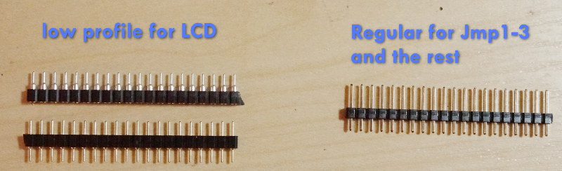
1 . Don’t mix the 20 pins regular male header with the 20 pins low-profile male and female header.
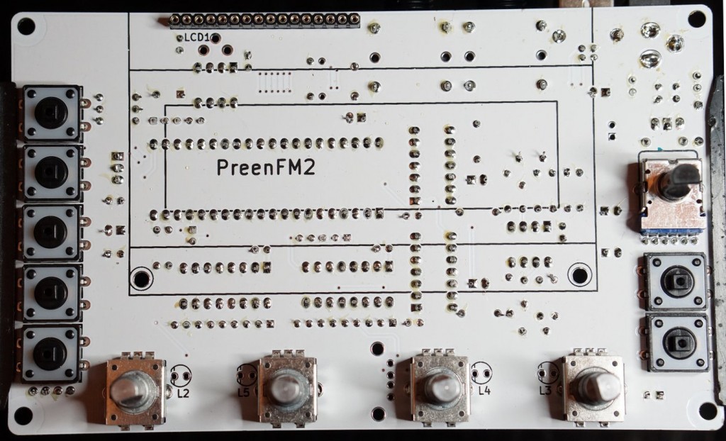
2 . Keep in mind that most components will be solder on the front side except :
- The LCD connector
- The volume pot
- The 4 rotary encoders
- The 7 switches
The rest is on the front side. It happened to me to solder the volume pot on the wrong side in the hurry, it was very difficult to unsolder it.
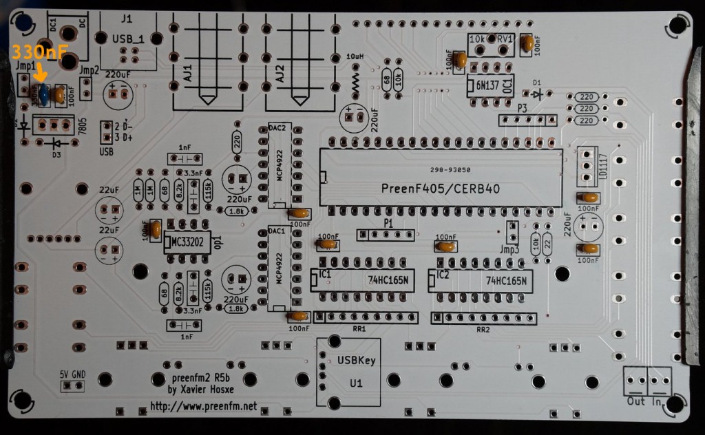
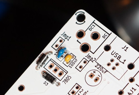
OK, that being said, let’s start by soldering the 10 declouping 100nF capacitors and the 330nF one that is recommanded in the 7805 regulator spec..
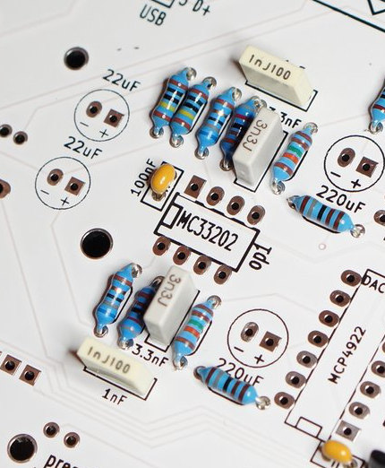
After that, you can sodler the resistors. Start by taking your multimeter to clearly identify the different resistor values.
Some of them are very important in the output stage.
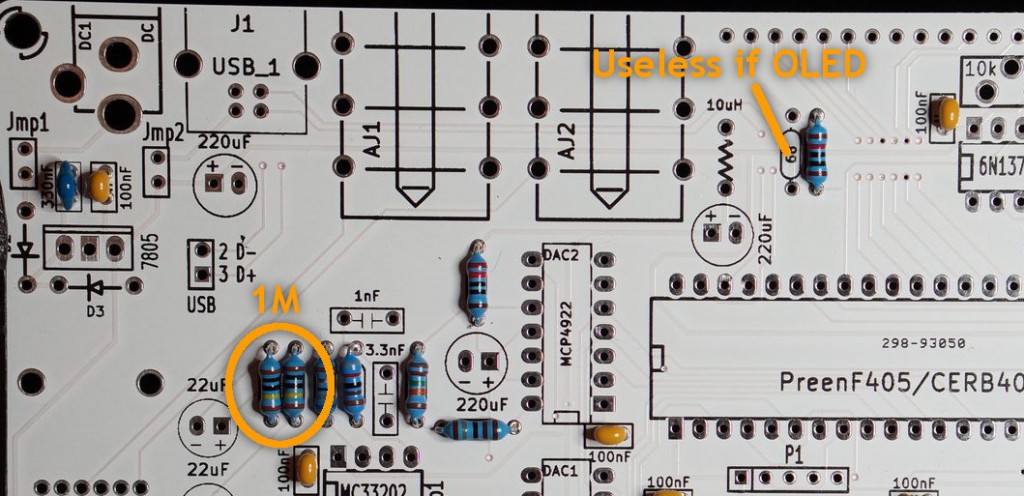
The smallest ones. Note that there is a 68 ohm that remains empty. It’s useless if you use a OLED display but must be added for LCD one.
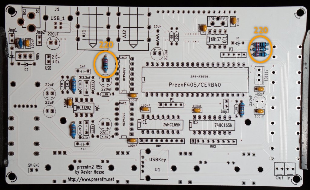
Then the four 220 ohms.
The two 10k : one for the midi Din5 and other one for the controller.
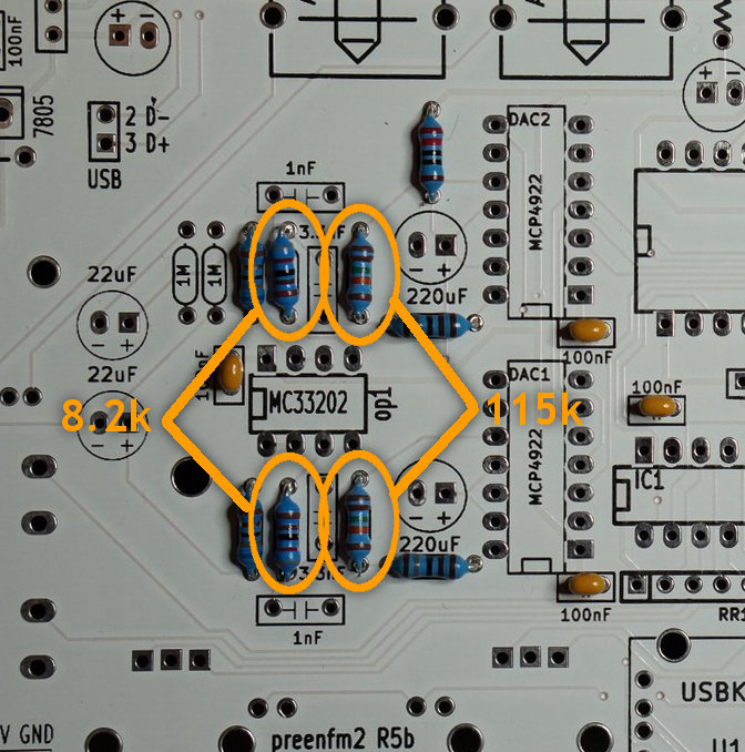
The two 1.8k: makes a 1/64 ratio with the 115K ones.
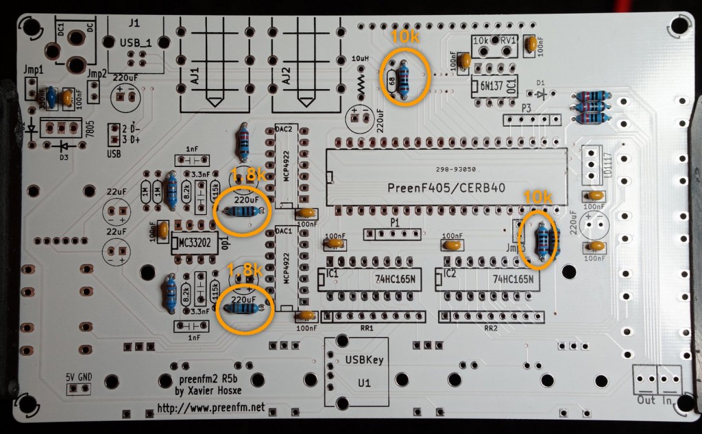
Two 115K for the DAC sums.
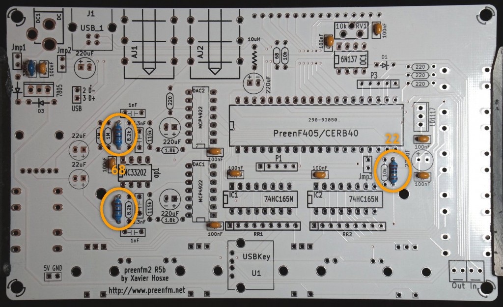
Two 8.2k for the antialising filter.
And the two 1M.
Now you can put the 3 diodes, D1 is the small red one, D2 and D3 the bigger black and white.
Orientation is very important, don’t miss the black ring on D1 that must respect the orientation drawn on the PCB.
The 10uH is an inductor whose goal is to add isolation to the audio part of the PCB.
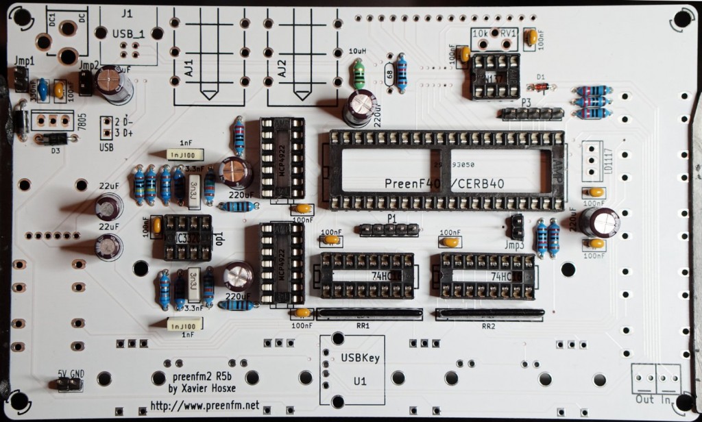
If you have a PCB revision R5d, you’ll have an additional resistor named Oled on the right of the above picture .
Populate it with a 22 ohm if you have an OLED display or shortcut it with a resistor pin if you have a LCD display.
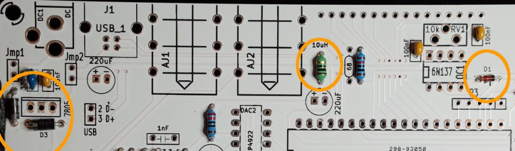
Mind the silver ring on D2 and D3:
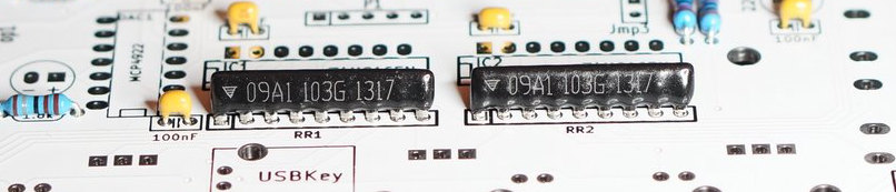
Then take the 2 resistor networks and put them like on this picture, the orientation is VERY important. The triangle of the 9 pins resistors must be over the left pin of the PCB (the pin that is alone in the white square).
Now let’s solder the 4 plastic capacitors. With the resistors around and the operational amplifer, they make a low pass filter (20Khz) whose goal is to antialias the output of the DAC.
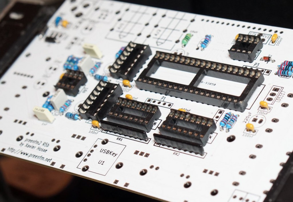
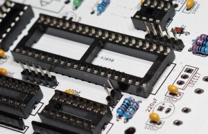
Then you can solder the 2 *DIP8, DIP14 *2, DIP16 *2 and DIP40 sockets. Respect the orientation so that it’s easier to put the ICs in the correct orientation too later.
Now take the male pins header and cut it into 3 pieces of 2 pins for jmp1, jmp2, jmp3. The rest is optional and you won’t likely need them.
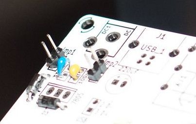
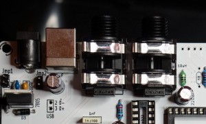
Jmp1 : The main current pass through this 2 pins. If you want to add a power switch this is the place. In any other case you want to have a connection here.
Jmp2 : This is the current from the USB plug. The 5V from the USB pass through it. If you want to enjoy the midi over USB while using a wall power supply (for exemple to control the PreenFM from an Ipod/Iphone/Ipad), it’s better to open Jmp2. That will avoid the 5V of the USB to be connected to the 5V of the regulator that can be a bit different.
In most case, you want the USB to power the PreenFM2, so the 2 pins must be connected.
Jmp3 : MUST NOT BE CONNECTED IN MOST CASES. If connected, the PreenFM will boot in the DFU (Device Firmware Update) mode integrated in the STM32F4 and your display will be all black. Useful to burn the bootloader and the firmware for the first time.
The three 2-pins headers for the jumpers should be installed, the rest is optional.
There is also a USB 2 pins socket on the right of the 7805 (top left of the PCB), these 2 pins must be unconnected if your STM32F4 board is a preenF405 (the one provided in the kit).
But if you have a CERB40 board you’ll need to wire them to the mini USB socket of the CERB40. See previous PCB soldering page for more info.
Now you can take the 7 electrolytic capacitors (2*22uF and 5*220uF). Mind the orientation.
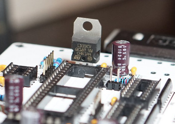
Then the regulators.. Double check you don’t mix the 7805 and the LD1117 (LD33CB).
The 7805 will convert the voltage of the power suply to 5V.
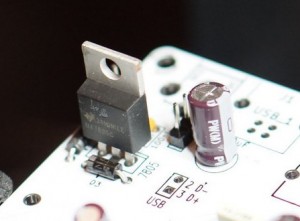
And the 3.3V regulator to power the microcontroller.
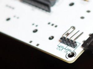
Now you can place place the DC connector, the USB socket and the 2 audio jacks :
A 4 pins right angle header can be used for the 4 bottom right holes. If you have the one from the kit, note that the shorter side must go in the PCB and the longer side outside.
The connection to the 2 Din5 Jacks is done in the Case build page.
At this point the USBKey socket is still not soldered. It’s better to first solder the controle surface then to come back to this component side and solder it with the USB stick plugged in.
Now flip over the PCB
(I forgot this at least twice while doing my prototype, and the build is dead !)
So flip over the PCB and add the 4 leds, the 7 switches, the volume pot and the 4 encoders.
Then encoders should enter smoothly in the holes, if it’s not the case, you may need to move closer to each other the 2 bigger pins.
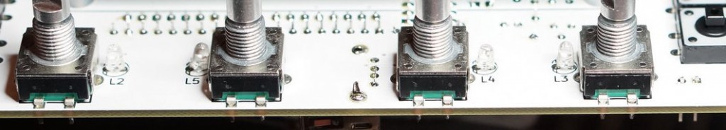
The minus of the led are drawn on the PCB, notice the aditional line. On the pictures the minus is the left pin.
The minus of the led is the shorter pin. Give a look at this if you hesitate : http://www.thediyworld.com/How-To-Properly-Use-LEDs.php
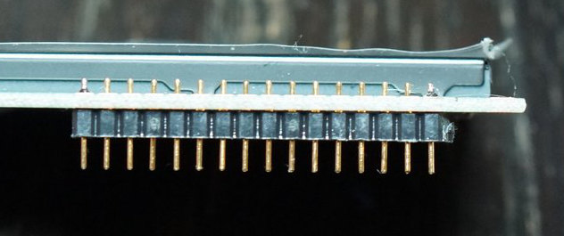
Then cut the low profile header for the LCD. Make the cut far from the 16th pin to be sure you do not cut the plastic around it.
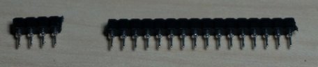
The low profile male header mut be perpendicular to the OLED display.
A good way to have this is to start by soldering only one pins.
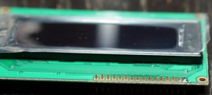
Then take the OLED in you hand and adjust the header while heating the pin you just soldered.
Be sure the header is as stuck as possible to the display and solder the 15 other pins.
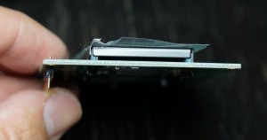
Then you can gently insert the OLED display.
On the opposite side of the display, use the 5mm spacers (or 8 mm (5+3) if you have the metal case) between the LCD and the PCB.
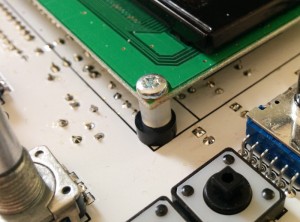
Be careful, the low profile header is quite fragile, so you should never force when inserting or removing the display.
Then flip over the PCB, solder the USB drive socket with your USB drive inside.
To fill the USB drive, download the zip file ‘pfm2_usb.zip’ (from the 2.08 release) and extract it on your drive, all files used by the preenfm2 is in a folder called ‘pfm2′.
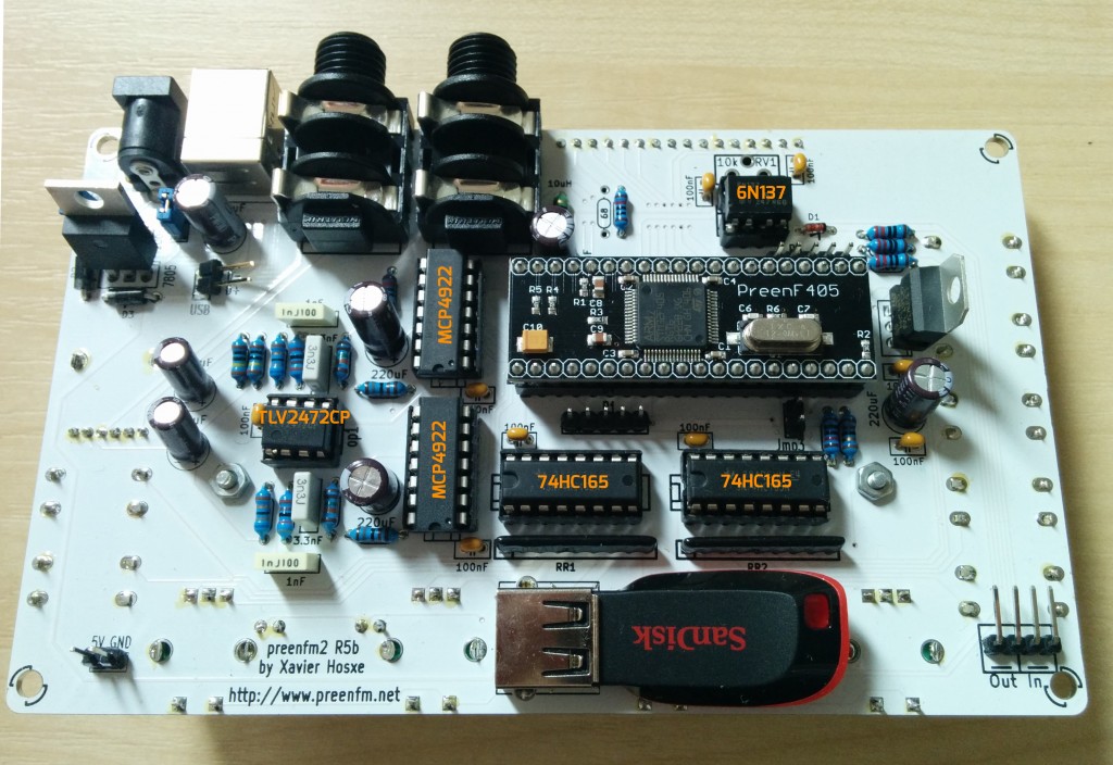
And you can insert the ICs.
Take your time for the preenF405/CERB40, at the begining it can seem very hard to insert, then the metal of the socket get softer and it’s easier.
The preenF405 provided with the kits is flashed with the bootlader 1.11 and the firmware 2.07 (or newer).
Check that your JMP3 is not connected, then plug the USB cable and you should be able to test everything is fine.
If your encoders does not respond properly see the 2nd entry of the FAQ ![]()